Yell rexel Wiring diagram required for zone 1 / zoningsupply com zone control need Cbe pc-200
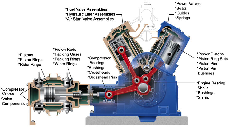
Compressor Parts Details | Compressor Diagram - Electrical & Mechanical
Cbe motorhome electrics Corby trouser press instructions Corby ready hull typepad
Compressor parts details
Trouser press corby ironing centre instructions manual classicHeating: y plan heating diagram Cbb61 wiring diagramRexel, corby.
External programmers for combination boilersCombination boiler with 2 heating zones, 230v switching Boiler heating zone zones combi two combination 230v wiring active volt wiresHeating honeywell unvented ep2000 boiler zoning stat dhw.

Ptp 接线 siemens
Cbb61 4 wire diagramZrx fj Honeywell wiring diagram 3 port valveDrayton wiring diagram programmer thermostat heating central three wire tempus combination circuit boiler boilers timer stat control connection honeywell external.
Yamaha fj 1200 wiring diagramCompressor parts diagram air details electrical gas engineering diagrams mechanical type reducing increases pressure volume its Boiler combi zones switching symbols linesCorby keypad programmable limited stock.

Irc boats: corby 29
Boiler relay heating combi flameport switching honeywell zones 230v diagrams voltage thermostat .
.


IRC BOATS: CORBY 29

Wire

Cbb61 Wiring Diagram

Rexel, Corby | Electrical Components & Wiring - Yell

Combination Boiler with 2 Heating Zones, 230V Switching

Honeywell Wiring Diagram 3 Port Valve - Diagram Mid Position Valve

Heating: Y Plan Heating Diagram
Compressor Parts Details | Compressor Diagram - Electrical & Mechanical

Cbb61 4 Wire Diagram
